
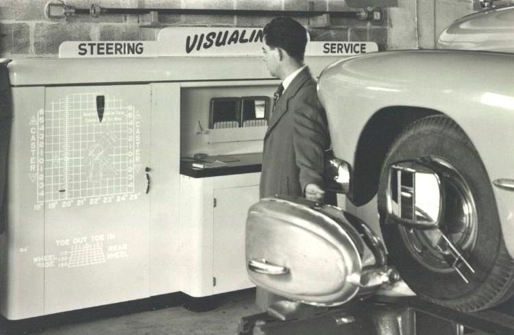
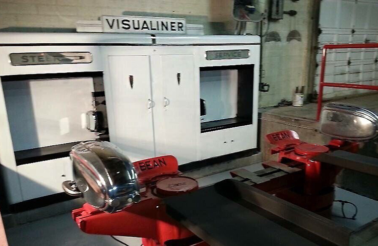
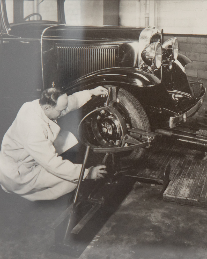
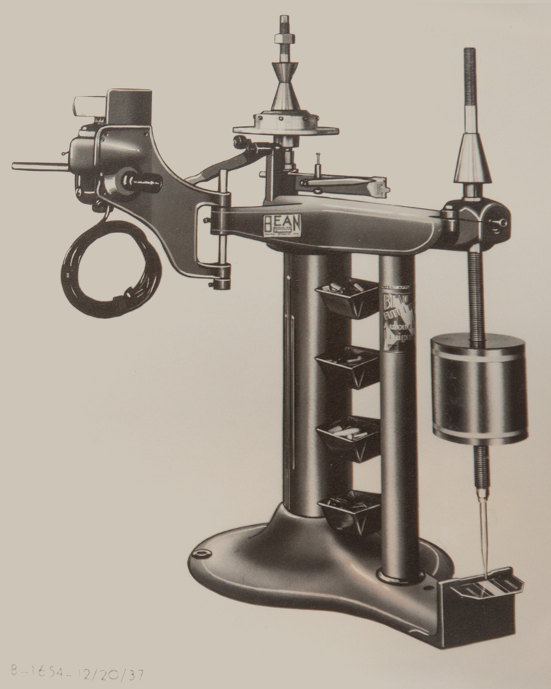
Magnified Readings, Projected for Clarity Precision crosshair targets displayed caster, camber, and toe measurements at a glance. Magnified readings projected onto a large screen allowed both operator and customer to clearly see the results—eliminating guesswork. The Visualiner® enabled quick, accurate checks, and simplified adjustments by allowing real-time visibility of corrections as they were made. Remote Access, Real-Time Results An all-new Remote-Control Unit came standard on the 1955 Visualiner® and was also offered as a convenient upgrade kit for earlier models. Introduced just a few years after the first light-based Visualiner® systems debuted, this innovation gave technicians fingertip control of alignment charts from beneath the vehicle, eliminating time wasted walking back and forth. By streamlining adjustments and reducing unnecessary steps, the Remote-Control Unit helped drive faster alignments and greater shop productivity. Photo #1263 (Mechanical Aligner): This photo captures an early mechanical aligner from John Bean-FMC, taken in the 1930s at their Lansing, Michigan engineering labs. A key contributor to the development of alignment systems, it paved the way for the Visualiner® and the modern computerized Visualiner® II, revolutionizing optical alignment technology. Photo #1265 (Wheel Balancer): This vintage image features the original Model 555 Wheel Balancer from John Bean-FMC, introduced in the 1930s. It was a cutting-edge tool at the time, designed to balance wheels and included convenient storage trays for weights, marking it as a pioneer in wheel service technology.
The Ingenious Dr. Bernie Jackson: From Apollo to the V3D Aligner Dr. Bernie Jackson, an engineer and entrepreneur, entered the wheel alignment industry with an astonishing background. His career began in astrophysics, contributing to the Apollo moon landing, where he designed the camera used during the mission. Afterward, Jackson turned his attention to creating the first generation of flight simulators—not the gaming systems we know today, but complex training systems used by pilots. His company thrived, but Jackson, always seeking new challenges, sold it and asked himself, “What’s next?” One day, while driving behind a vehicle with obvious dog-tracking and camber issues, Dr. Bernie Jackson had a flash of inspiration: “If I can see with my own eyes that this car needs alignment, I could use a camera and computer to calculate exactly how to adjust the wheels.” Drawing from his deep expertise in imaging systems and his work on 3D spatial calculations for the Apollo project, Jackson envisioned using a camera-based system to simplify and enhance alignment accuracy. He gathered a team of top experts in cameras, optics, and computer processing from Silicon Valley, where these technologies converged. His approach revolutionized the alignment industry. Jackson created the first camera-target-based aligner, marking a seismic shift in how wheel alignment was performed. Recognizing the value of his work, Snap-on acquired both Jackson’s company and his patents just as they were expanding the John Bean brand. This perfect convergence of timing and innovation ensured that Snap-on could leverage Jackson’s 3D technology to stay ahead of the competition. As a result, for the next 20 years, many Snap-on competitors licensed Jackson’s 3D camera-based alignment patents. Purpose: Represents the point at which the suspension pivots during steering. Adjustment: Fixed location. Used to identify suspension geometry and vehicle thrust angle; may also be referenced during damage analysis. Purpose: Indicates where the structure of the frame is attached to the suspension or vehicle body. Adjustment: Fixed. Used to assess structural damage or misalignment during repair or realignment. Purpose: Used to locate upper suspension mounting points. May also indicate shock tower or cowl panel. Adjustment: Fixed sheet metal. May sag or move slightly due to collision damage.
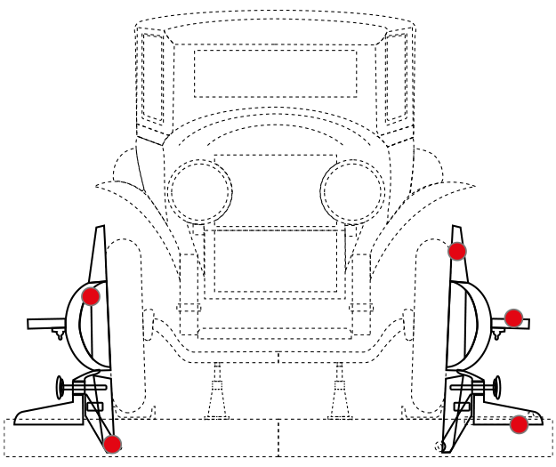
Purpose: Indicates the centerline of the wheel assembly and marks the wheel’s lateral position. This reference may vary slightly side-to-side. Adjustment: Fixed within the suspension system. Primarily used for measurement and to verify lateral symmetry between the left and right wheels. Purpose: Same as the frame anchor point on the left side. Adjustment: Fixed. Used as a reference for locating suspension and steering components during pushing or alignment. Purpose: Represents the point at which the suspension pivots during steering. Adjustment: Fixed location. Used to identify suspension geometry and vehicle thrust angle; may also be referenced during damage analysis. Purpose: Indicates where the structure of the frame is attached to the suspension or vehicle body. Adjustment: Fixed. Used to assess structural damage or misalignment during repair or realignment. Purpose: Used to locate upper suspension mounting points. May also indicate shock tower or cowl panel. Adjustment: Fixed sheet metal. May sag or move slightly due to collision damage.
Purpose: Indicates the centerline of the wheel assembly and marks the wheel’s lateral position. This reference may vary slightly side-to-side. Adjustment: Fixed within the suspension system. Primarily used for measurement and to verify lateral symmetry between the left and right wheels. Purpose: Same as the frame anchor point on the left side. Adjustment: Fixed. Used as a reference for locating suspension and steering components during pushing or alignment. Purpose: Represents the point at which the suspension pivots during steering. Adjustment: Fixed location. Used to identify suspension geometry and vehicle thrust angle; may also be referenced during damage analysis. Purpose: Indicates where the structure of the frame is attached to the suspension or vehicle body. Adjustment: Fixed. Used to assess structural damage or misalignment during repair or realignment. Purpose: Used to locate upper suspension mounting points. May also indicate shock tower or cowl panel. Adjustment: Fixed sheet metal. May sag or move slightly due to collision damage.
Purpose: Indicates the centerline of the wheel assembly and marks the wheel’s lateral position. This reference may vary slightly side-to-side. Adjustment: Fixed within the suspension system. Primarily used for measurement and to verify lateral symmetry between the left and right wheels. Purpose: Same as the frame anchor point on the left side. Adjustment: Fixed. Used as a reference for locating suspension and steering components during pushing or alignment.

John Bean Wheel Alignment

Spindle Pivot
Anchor Point
Cowl Mount
Centerline
Anchor Point
Spindle Pivot
Anchor Point
Cowl Mount
Centerline
Anchor Point
Spindle Pivot
Anchor Point
Cowl Mount
Centerline
Anchor Point

John Bean
Today!
A century
in motion
Wheel Alignment
through the
1925
John Bean, originally a spray pump manufacturer, transitioned to designing water pumps for fire trucks. He noticed that the long wheelbases of these vehicles required more precise alignment than traditional methods like strings and tape measures could offer. In 1925, he invented the first mechanical wheel aligner, which measured camber, toe, and caster by physically contacting the wheels, establishing the foundation for the John Bean alignment system.
2025
The John Bean legacy continues to shape modern technology. The latest aligner, building on the John Bean 3D imaging foundation, incorporates D2Max™ technology to map vehicles in real-time, simulating road conditions. Unlike early 3D aligners that captured static images, this system enables technicians to detect tyre wear and alignment issues with unmatched precision, ensuring accurate adjustments as if the vehicle were driving on the road.
Milestones: the History of
1925
John Bean, recognising the limitations of rudimentary alignment tools like strings and tape measures, invented the first mechanical wheel aligner to meet the precise needs of long-wheelbase fire trucks. This device made physical contact with wheels to measure camber, toe, and caster, revolutionising alignment accuracy and establishing the foundation for modern alignment systems. This innovation addressed the growing demand for precision in heavy-duty vehicles, marking John Bean as a pioneer in automotive service technology.
Snap-on® acquired John Bean, combining alignment expertise with Dr. Bernie Jackson’s pioneering 3D imaging technology. This merger launched a new era in wheel alignment, blending mechanical systems with patented high-definition camera tech for faster, more accurate service. The resulting platform set a new industry standard, as imaging alignment quickly became the benchmark. Innovative solutions from John Bean led to widespread adoption across the industry, with many competitors licensing the technology over the next two decades.
1996
2008
The Prism™ on-car wheel aligner changed the alignment market yet again, combining key features of charge coupled device (CCD) systems with 3D imaging technology in a compact, mobile solution. As the world’s first on-vehicle imaging alignment system, Prism™ delivered the speed, precision, and diagnostic power of fixed imaging systems in a flexible, technician-friendly format. Lightweight magnesium pods and targets minimised fatigue and enabled alignments in half the time of traditional systems. Designed for efficiency, Prism™ operated across multiple bays without recalibration, maintaining accuracy even at extended distances. This innovation reinforced John Bean as a leader in alignment technology.
John Bean introduced the V3300 Wheel Alignment System, combining its fastest-ever imaging technology with intelligent software to guide technicians of all skill levels through the alignment process. Real-time alerts reduce errors and speed up procedures, allowing shops to complete more alignments with greater accuracy and efficiency. The system also delivers instant access to critical OEM data—including repair info, TSBs, recalls, TPMS resets, and vehicle-specific ADAS calibration procedures—eliminating guesswork and improving productivity across the board.
2016
2025
Launched in 2025, the all-new V4400 Commander™ from John Bean features D2 Max™ Technology, which maps and projects the vehicle’s drive direction as if on the road. Its dual-tower design with two remote alignment posts and high-resolution cameras eliminates the need for a cross-view camera. Building on Dr. Bernie Jackson’s 3D imaging legacy, the system enhances precision in detecting tyre wear and alignment issues, helping reduce comebacks and streamline workflows. AIKnow™ Companion, advanced notifications, and real-time OEM repair access further boost productivity, reinforcing the commitment to innovation that defines the John Bean brand.
1925
John Bean, recognising the limitations of rudimentary alignment tools like strings and tape measures, invented the first mechanical wheel aligner to meet the precise needs of long-wheelbase fire trucks. This device made physical contact with wheels to measure camber, toe, and caster, revolutionising alignment accuracy and establishing the foundation for modern alignment systems. This innovation addressed the growing demand for precision in heavy-duty vehicles, marking John Bean as a pioneer in automotive service technology.
1996
Snap-on® acquired John Bean, combining alignment expertise with Dr. Bernie Jackson’s pioneering 3D imaging technology. This merger launched a new era in wheel alignment, blending mechanical systems with patented high-definition camera tech for faster, more accurate service. The resulting platform set a new industry standard, as imaging alignment quickly became the benchmark. Innovative solutions from John Bean led to widespread adoption across the industry, with many competitors licensing the technology over the next two decades.
2008
The Prism™ on-car wheel aligner changed the alignment market yet again, combining key features of charge coupled device (CCD) systems with 3D imaging technology in a compact, mobile solution. As the world’s first on-vehicle imaging alignment system, Prism™ delivered the speed, precision, and diagnostic power of fixed imaging systems in a flexible, technician-friendly format. Lightweight magnesium pods and targets minimised fatigue and enabled alignments in half the time of traditional systems. Designed for efficiency, Prism™ operated across multiple bays without recalibration, maintaining accuracy even at extended distances. This innovation reinforced John Bean as a leader in alignment technology.
2016
John Bean introduced the V3300 Wheel Alignment System, combining its fastest-ever imaging technology with intelligent software to guide technicians of all skill levels through the alignment process. Real-time alerts reduce errors and speed up procedures, allowing shops to complete more alignments with greater accuracy and efficiency. The system also delivers instant access to critical OEM data—including repair info, TSBs, recalls, TPMS resets, and vehicle-specific ADAS calibration procedures—eliminating guesswork and improving productivity across the board.
2025
Launched in 2025, the all-new V4400 Commander™ from John Bean features D2 Max™ Technology, which maps and projects the vehicle’s drive direction as if on the road. Its dual-tower design with two remote alignment posts and high-resolution cameras eliminates the need for a cross-view camera. Building on Dr. Bernie Jackson’s 3D imaging legacy, the system enhances precision in detecting tyre wear and alignment issues, helping reduce comebacks and streamline workflows. AIKnow™ Companion, advanced notifications, and real-time OEM repair access further boost productivity, reinforcing the commitment to innovation that defines the John Bean brand.
John Bean Red Dot Reference Guide:
Key Measurement Points for Frame Alignment and Inspection
Kingpin/
Frame
Fender Liner or
Wheel Hub
Frame
Tap the buttons to learn more
Kingpin/
Frame
Fender Liner or
Wheel Hub
Frame
Tap the buttons to learn more
Kingpin/
Frame
Fender Liner or
Wheel Hub
Frame
Contact